When developing software, performance is one of the most important facets, especially if targeting a platform like web/mobile.
Creating and Destroying objects requires a lot of memory and processing power relative to our other game actions, but we can reduce the impact of Instantiation in Unity by simply reusing them.
In Unity, we can do this by Instantiating all of the objects first, then storing references to them.
We will explore this concept in an example open source game I created ‘slashdot’, which also contains shaders from the last two posts.
We will begin creating the class which will actually handle our pooled objects. When working with pooled GameObjects vs simply Instantiating and Destroying them, we want to be careful of a few key concepts. Firstly, we want to disable most properties for reuse later as opposed to destructing them. Rarely you will need to create and destroy components on initialization, but the vast majority of components or the GameObject itself can be disabled and enabled.
public GameObject enemyPrefab;
public Queue<Enemy> PooledEnemies;
public List<Enemy> TrackedActiveEnemies;
Assign an enemy through the inspector. Next we will create our pools.
Creating the Objects
Call the setup function in the Awake of the class to setup the pool.
void SetupPools()
{
    for (int i = 0; i < 100; i++)
    {
        var enemy = Instantiate(enemyPrefab, Vector3.zero, Quaternion.identity);
        PooledEnemies.Add(enemy.GetComponent<Enemy>());
        enemy.SetActive(false);
    }
}
This will Instantiate all of the objects and keep a reference for us.
Using the Objects
Now, when we want to use a GameObject we can simply call our function in our class from our instance to return a GameObject for us to manipulate.
A super simple implementation might look something like the below.
If only using the <Queue> type and planning for one enemy. However, we want to use multiple enemy types. We can make our pooled enemies a list to have more flexibility. An example implementation for this logic would be an EnemyType enum that the GetEnemy function checks, like so.
public List<Enemy> PooledEnemies = new List<Enemy>();
public GameObject GetEnemy(Enemy.EnemyType enemyType)
{
    foreach (var enemy in PooledEnemies)
    {
        if (enemy.CurrentEnemyType == enemyType)
        {
            PooledEnemies.Remove(enemy);
            return enemy.gameObject;
        }
    }
}
Now we can simply use this as we would an instantiated object.
randomEnemyType = Random.Range(0, 3) == 0 ? 1 : 0;
var enemy = GetEnemy((Enemy.EnemyType)randomEnemyType);
enemy.transform.position = new Vector3(Random.Range(0,100), Random.Range(0,100), enemy.transform.position.y, 0f);
enemy.SetActive(true);
var enemyComponent = enemy.GetComponent<Enemy>();
enemyComponent.Init();
TrackedActiveEnemies.Add(enemyComponent);
Returning the Object to the Pool
We can use a function like the one below to return a used object to the pool after we are done with it.
public void RemoveEnemy(Enemy enemy)
{
    enemy.gameObject.SetActive(false);

    TrackedActiveEnemies.Remove(enemy);
    PooledEnemies.Add(enemy);
}
Simply call RemovePooledEnemy() wherever needed.
Manager.Instance.RemoveEnemy(this);
Re-using Objects
Most of the quirks that you’ll encounter from pooling GameObjects like this stem from figuring out how to reset everything nicely. Unity doesn’t run most code on disabled objects; it’s usually preferable to reset things on Init to avoid unexpected behavior.
I recently saw these UI effects in a game called Cult of the Lamb and they were very satisfying to watch. Let’s learn how to create our own types of effects like these.
We want to begin with a base shader to manipulate, so let’s start by displaying a sprite.
Our shader must expose it to the editor in order to set our texture. Add a line under our properties defining a main texture.
_MainTex ("Base (RGB) Trans (A)", 2D) = "white" {}
And the variable under SubShader.
sampler2D _MainTex;
float4 _MainTex_ST;
The _ST value will contain the tiling and offset fields for the material texture properties. This information is passed into our shader in the format we specified.
We want to add some movement and distortion to our sprite. Begin with movement.
How can we manipulate our shader pixels? Let’s show an example by modifying our main texture. We’ll simply change the position. To do so, we can do something simple like shifting the texture coordinate down and to the left.
If you examine your sprite at this point, you may notice some odd distortion as it moves.
Set your sprite’s import settings correctly! Mesh Type: Full Rect Wrap Mode: Repeat
Once you ensure your sprite has the correct import settings, it’s time to introduce our final 2d sprite we want to manipulate with the shader to achieve our effect.
This image will greatly change the shader appearance, and you should try different gradients and patterns. Here’s my image scaled up:
But I recommend using the smallest resolution that looks good for your project due to memory and performance.
yes it’s that small (12×12)
We also need a seamless noise texture, for the distortion.
Let’s add another variable for it.
_NoiseTex ("Base (RGB) Trans (A)", 2D) = "white" {}
Once we’ve assigned our noise texture, it’s time to start moving it.
Shaders can be a useful way to enhance the visual presentation of your project through subtle or otherwise effects. Beyond code, the engine provides a built in visual scripting tool to create shaders from version 2019 onwards.
We will create an effect that allows us to highlight the player and obscure the rest of our stage. With scripting, we can also modify our exposed shader properties to adjust the intensity of the transparency effect, and transition to having no highlight. Examples will be shown later in the post.
Prerequisites
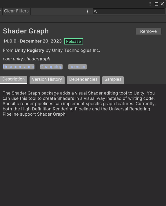
Ensure you have the Shader Graph package installed in your version of Unity. I am using 2022.3.17f for this post.
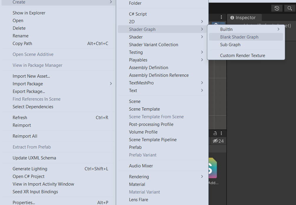
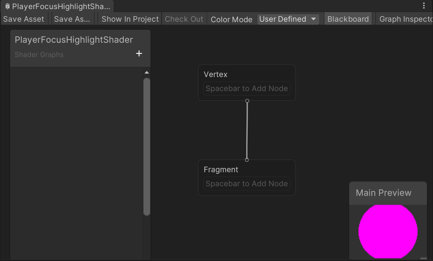
Creating the Shader
Right click in your Unity Project and do Create > Shader Graph > Blank Shader Graph
Now that we have a Shader Graph file, simply open the editor by double clicking it.
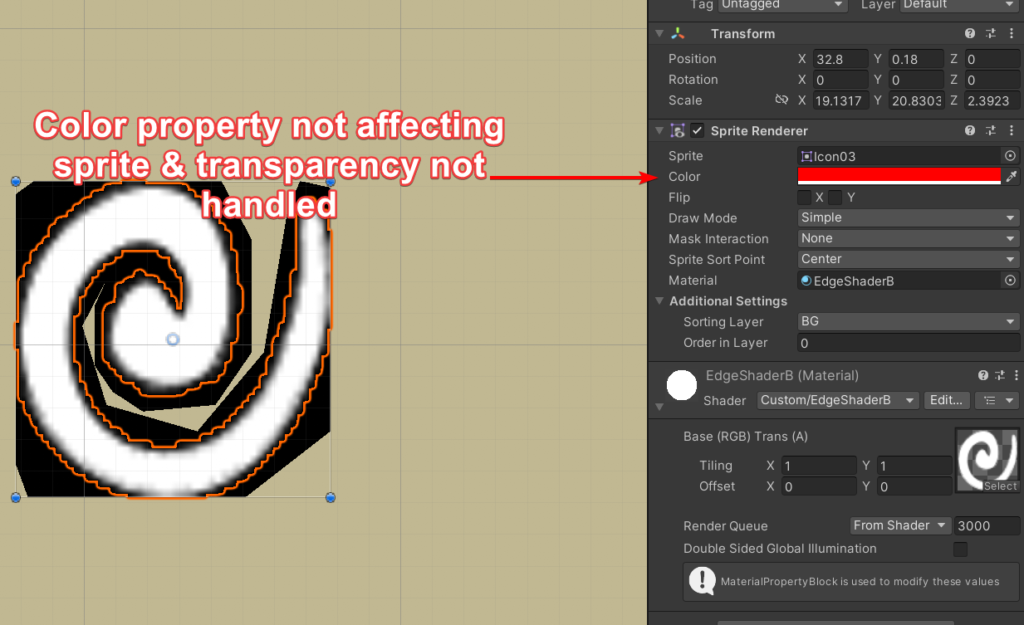
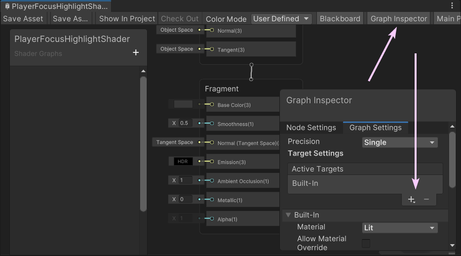
Let’s add some basic shader properties first. Navigate to the Graph Settings and add Built In as a target. We want the ability to control the transparency of our pixels, so also add the Alpha property to our fragment.
In order to properly utilize the Alpha property, we will need to edit the Built In settings Surface Type to Transparent.
Shader Inputs
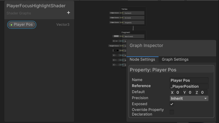
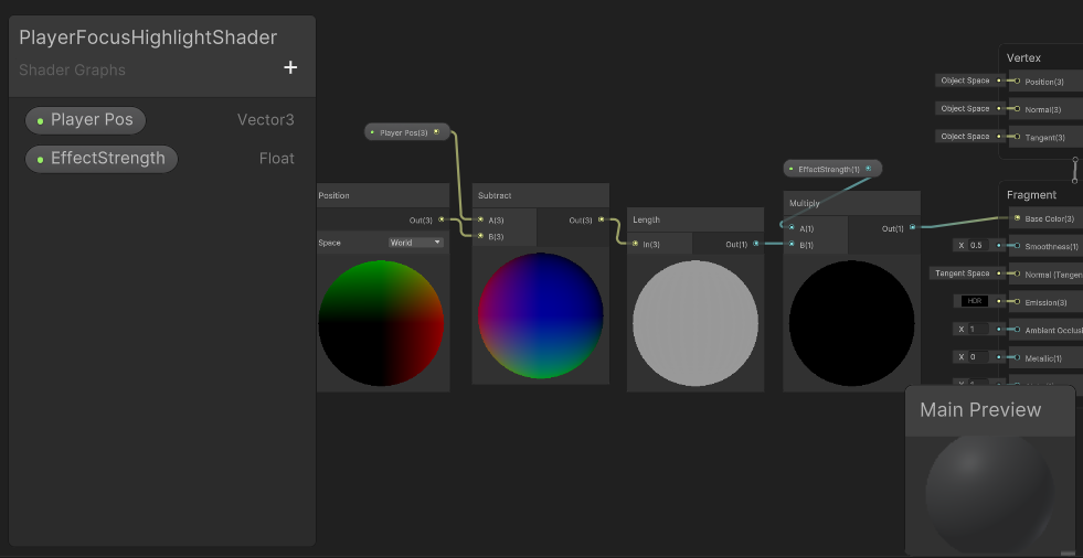
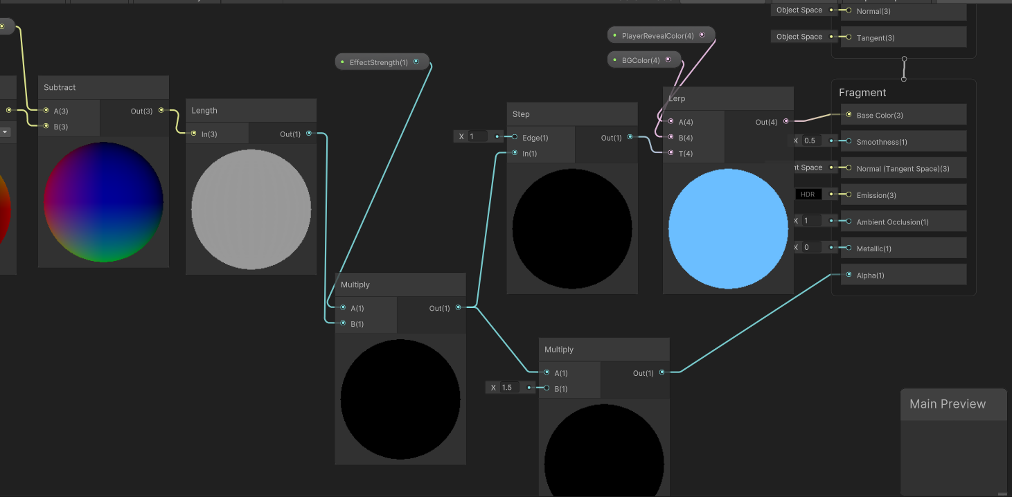
The first thing to consider is the Player’s world position. Since we want the highlight effect to follow the player, we’ll need some sort of input into the shader.
In the Shader Graph editor, ensure the ‘Blackboard’ option is checked and visible, then click the plus button on the left side of the editor to create an input variable. Make it a Vector3 category. The ‘Name’ is for visual purposes, and the ‘Reference’ field will allow scripts access to the property. Give that some value like “_PlayerPosition” and drag it into the stage.
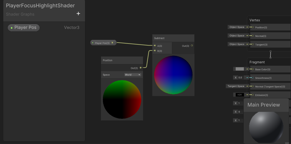
Since that’s simply a Vector, we need to translate that into something usable for our shader. We need to subtract the input player position from our world position so we can get the individual area to affect.
Right click, and create a Position and Subtract node.
Connect the player position and world position node to the subtract node. At this point your graph should look similar to below.
Next we will need a Length node to translate our position into a distance.
At this point, if we connect the output of our length to our Base Color on our Fragment, we can see a strange divine light.
How can we control the actual effect size?
We need a multiply node and some additional input here to control the highlight amount.
Let’s create a new Multiply node, and a Float input.
Name the Float input something like _EffectStrength, and feed the length output into the new multiply node.
You should have something similar to this, and the shader will go black again. This is simply because we haven’t given it an effect strength yet.
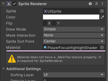
Save this Shader Graph asset and assign it to an object in our scene if you haven’t already.
Notice the warning. This refers to the fact that we aren’t rendering a sprite. This is correct, and can be safely ignored.
Assuming a reference to the sprite renderer component, we can then use the material set property functions to pass along our game values in an Update function or whenever needed.
Set the effect to something visible like 1 for now. We can also set a default through the Shader Graph editor.
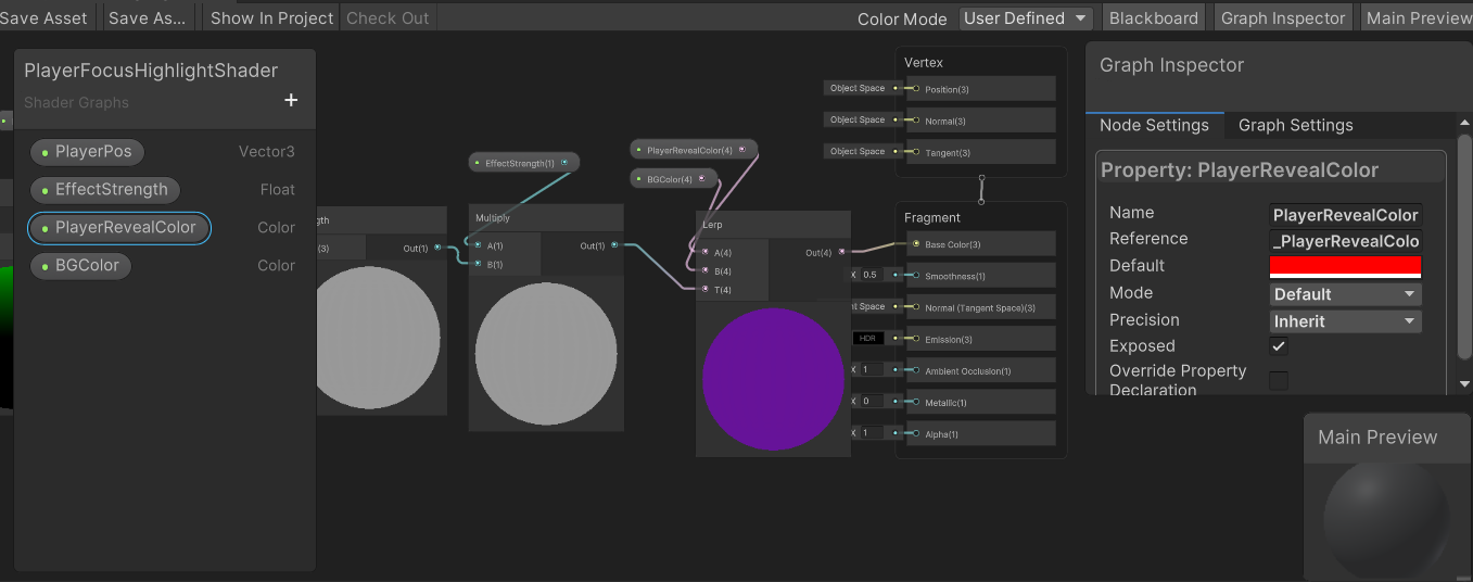
All of this grey is pretty boring, so let’s add some color. The ability to edit our colors through scripting is pretty important, so let’s create two new Color variables.
The shader will lerp between these two colors for the highlight effect. We could use only one color considering our goal of mixing the effect with transparency, but the additional color gives more control over the effect appearance.
Create a Lerp node. Connect the output of the previous multiply node to the lerp T input, and the two new colors to the A and B inputs, respectively.
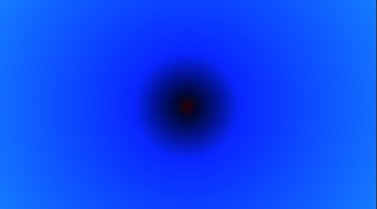
I set BGColor to blue, and PlayerRevealColor to red through the graph inspector to clearly show the shader effect.
If all goes well, you should have a circular gradient in the input colors you’ve specified.
And something like this in your Shader Graph.
That gradient isn’t really the look we want. Instead, we want a tight circular highlight around the player position.
To achieve this, we can add a Step node.
Insert it between the multiply and lerp node at the end, and it will produce a gated circular output.
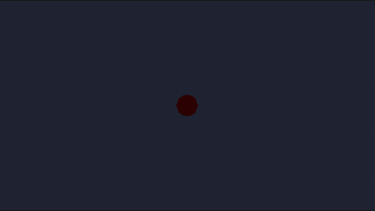
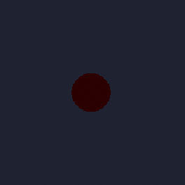
Adjusting the EffectStrength should make the circle appear larger. Try values from 0 -> 1. Above 1 will make the highlight smaller.
EffectStrength at 0.5
EffectStrength at 0
Now we just need to connect our transparency logic.
Add another Multiply node that we will use for the Alpha property on the Fragment. The input should be our previous multiply node’s output, before the Step node. This allows control over the strength of the highlight fade. I went with 1.5.
You’re pretty much finished!
We can adjust the colors to do screen wave effects like this that could be enhanced with particle effects.
Or as a game over effect where you hide the rest of the stage and highlight the player. I added a purple background sprite behind the player to show the masking effect.
Force fields, lights for dark mazes etc all follow a similar concept.
$125 is a chunk of change. $125/month is even more. When a monthly subscription is offered, it’s because that subscription is consistently bringing in value.
This is exactly what Unity3D, a widely used game engine, is asking from “freelancers”. They recommend using their “Pro” tier, which is $125 per month, if you’re in a team or you’re a “freelancer”, whatever they define that to be.
If you’re a “hobbyist”, you should apparently pay $35 a month, or ~$25 per month if you prepay for a year.
If you’re a “beginner” (or don’t have $300 laying around to pay per year), then you should use the free version.
Now, let’s talk about benefits that these versions give you.
This screenshot may be out of date to their current pricing.
The Unity page lists “benefits” of their Pro and Plus versions, while listing nothing for the Personal version. However, in my opinion, the benefits listed are virtually worthless. I have never used or wanted to use any of them, and I own the Plus version.
Here are my “benefits” that I get with my Plus license:
Support to accelerate learning & development
Benefits with Prepaid plan only:
Learn the essentials of game development with 12 months access to Unity Game Dev Courses ($144 value)
Get 25GB Unity Cloud Storage ($60 value)
Attend monthly Expert Live Sessions. Speed up your development with technical know-how from Unity engineers ($240 value)
Limited access to a Customer Success Advisor: get help finding the tools and resources you need to succeed
Save 20% on top-rated assets in the Asset Store*
Personally, I don’t care about any of these things. You might. However, there are two features I DO care about, being a professional software engineer who wants the things they make to look polished.
Some of you may think, “so what?”, but I can tell you that the light theme is an absolute eye-sore, especially if you’ve been staring at a screen for 8 hours.
The Splash Screen
And of course, the main reason why everyone who’s serious about developing games purchases a license for Unity: the splash screen.
You see, Unity forces non-subscribers to display an obnoxious “Made with Unity” or “Powered by Unity” (depending on which version of said engine you have), that looks something like this:
This is a bad move. You may be thinking to yourself right about now: “Well, makes sense, because they want to get at least SOMETHING out of distributing their engine for free. Why not popularity?”
This is true. Except it will be bad popularity. Let’s walk through this.
Let’s imagine there are two people using Unity. Bob, who has never developed anything in his life, and Kyle, who is a professional at developing games. Bob makes a crappy little box simulation with built in assets and it runs like crap because it is crap. No offense to Bob, he’s just completely new to developing games. He’s also using the personal version of Unity, obviously, because he’s brand new and wants to try to make something cool. He happily publishes his creation online, and some people download his game and see what an absolute mess it is. They also notice a very large, long, “Made with Unity” splash screen that displays for five seconds. Their parting thoughts? “Wow, Unity must be for people who don’t know how to make games.”
Kyle, on the other hand, is a professional. He buys Unity Plus for ~$25 a month because he hates the Unity splash screen, and wants to remove it so that he can put his own splash screen or logo. When Kyle uploads his professionally made, polished game, people enjoy it. And they also don’t know it’s made with Unity, because he removed it.
Notice a pattern here? Unity has received a very bad reputation among the gamer community (and somehow no one can figure out why), because every terrible game ever has a “Made with Unity” splash screen. What Unity SHOULD be doing, is PAYING developers such as the ones who made Cuphead (which is made with Unity if you didn’t know before) to put the Unity Splash on their game, and letting beginners remove it. Beat Saber is an immensely popular VR game that is made with Unity, but no general consumer is aware of that fact. Unity should be trying to control the positive PR as much as possible to drive more developers to their platform and rid the “terrible game engine” stigma from the engine’s name.
Unity states that they’re “the world’s leading real-time engine”, and is “used to create half of the world’s games”. They might want to start trying to put their name on the good ones.
I recently acquired a VIVE and after a day of oohing and ahing about how cool it was, began to create some simulations for it in Unity. The first of such is located on my main site, along with a demo video in case you don’t have a VR headset. You should definitely check it out.
I discovered a couple of things. First, I’m totally sold on VR being the future. I don’t get motion sick (at least while not moving from a fixed point in VR, more on this in a bit) , so I’m fine to whip my head around in Virtual Reality all I want. The experience is really cool, and tricked my brain into thinking I was somewhere else much more than expected. I first picked up a jetpack and immediately got butterflies in my stomach, because I felt like I was actually flying upwards! Over the next couple of years VR tech will improve drastically, just like all new devices. A few areas that could improve are portability, resolution of the eye pieces, and performance on lower end devices. We will also see advancements in handling sound. Currently you need to provide your own headphones and it’s a bit of a clunky setup.
VR Development Best Practices
So, what’s actually different about VR development? Beyond the obvious need for different gameplay design, there are some key details that devs might overlook. I refer to Unity with these points but they can be adapted to other engines, as conceptually they are the same.
Performance
Performance is much more important in VR than typical game design. This is because if the display lags, it can induce physical discomfort and nausea in some users.
Rendering
Rendering is one of the most recurring bottlenecks in VR projects. Optimizing rendering is essential to building a comfortable and enjoyable experience in VR. In Unity, “setting Stereo Rendering Method to Single Pass Instanced or Single Pass in the XR Settings section of Player Settings will allow for performance gains on the CPU and GPU.
Lighting
Every lighting strategy has its pros, cons, and implications. Don’t use full realtime lighting and realtime global illumination in your VR project. This impacts rendering performance. For most projects, favor the use of non-directional lightmaps for static objects and the use of light probes for dynamic objects instead.
Post-Processing
In VR, image effects are expensive as they are rendering the scene twice – once for each eye. Many post-processes require full screen draws, so reducing the number of post-processing passes helps overall rendering performance. Full-frame post process effects are very expensive and should be used sparingly.
Anti-aliasing is a must in VR as it helps to smooth the image, reduce jagged edges, and improve the “look” for the user. The performance hit is worth the increase in quality.
Cameras
Orientation and position (for platforms supporting 6 degrees of freedom) should always respond to the user’s motion, no matter which of camera viewpoint is used.
Actions that affect camera movement without user interaction can lead to simulation sickness. Avoid using camera effects similar to “Walking Bob” commonly found in first-person shooter games, camera zoom effects, camera shake events, and cinematic cameras. Raw input from the user should always be respected.
Unity obtains the stereo projection matrices from the VR SDKs directly. Overriding the field of view manually is not allowed.
Depth of field or motion blur post-process effects affect a user’s sight and often lead to simulation sickness. These effects are often used to simulate what your eyes do naturally, and attempting to replicate them in a VR environment is disorienting.
Moving or rotating the horizon line or other large components of the environment can affect the user’s sense of stability and should be avoided.
Set the near clip plane of the first-person camera(s) to the minimal acceptable value for correct rendering of objects. Test how it feels to put an object into your face in VR. Set your far clip plane to a value that optimizes frustum culling.
When using a Canvas, favor World Space render mode over Screen Space render modes, as it very difficult for a user to focus on Screen Space UI.
UI
More on that last bullet point above.
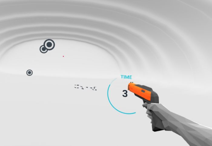
Something very interesting about VR is the need for a Diegetic UI. A Diegetic UI means a user interface that exists in the universe (in this case, a game) that we are experiencing. So, a non-Diegetic UI would be your health floating at the bottom left of your screen on a normal computer game.
Now here’s the problem. In VR: your eyes can’t focus on something that close. Putting something on screen close to the face of the viewer works really well for normal games where you can focus on the screen at a specific part. However, VR goggles work by projecting two separate images on each lens, and your brain combines it to achieve depth perception. Putting something that statically close to the screen makes the user’s eye attempt to focus on it, which makes the viewer go cross-eyed and the whole immersion is broken. The solution? Use diegetic UI elements. What this means is attaching the UI to objects IN the game world. This looks really cool, and accomplishes the goal of not breaking immersion and looking terrible.
Notice the time left is stuck to the gun, so the user can look at the UI themselves vs it being stuck on the screen
This type of UI hasn’t been limited to VR either, it just works really well in it. We’ve seen examples of this kind of user interface all over.
VR will hit mainstream within 20 years, and we will see long term usage within 50.